Overview
In this project we had to create a circuit that produces an output only if there's majority vote. In the event that there is a tie the president's vote serves as a tie breaker. The vote is split between four people, the President (P), the Vice President (V), the Secretary (S), and the Treasurer (T).
Problem Conception
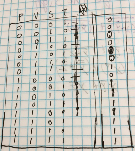
This truth table shows under which conditions the circuit will work. the relation between the number of variables and the number of rows is that where the number of terms equals n, the number of rows is 2^n. when there are two votes the decision can either be 1 or 0. Since the president is the one who decides if it will pass of fail, one can assume that if the president is one of the two then it will pass.
|
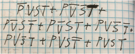
This is the un-simplified logic expression that represents the truth table shown to the left. I got this by writing down the minterms that resulted in the desired result. This is written in a sum of products form because it is easier to use this form to create a logic circuit.
|
|
Unsimplified Circuit
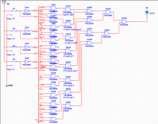
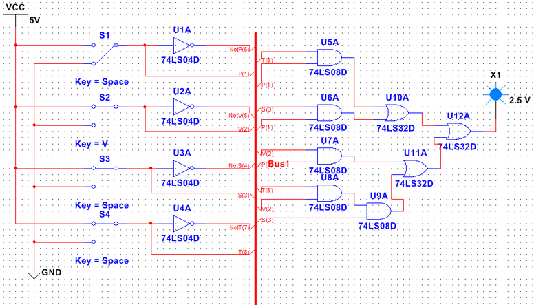
This circuit was created using multisim and represent the logic expression given above. It was created using a bus because it makes the diagram look less chaotic and prettier. this design uses 4 inverter gates, 24 AND gates, and 7 OR gates.
Based on the number of gates, one would need one 74LS04 Inverter chip, six 74LS08 AND gates, and 2 74LS32 OR gates. |
|
Boolean Algebra
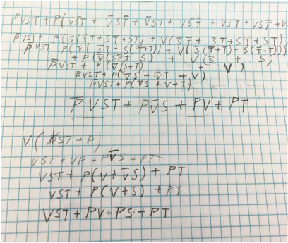
Next we had to simplify the logic expression derived from the truth table. i used Boolean theorems such as X*X=X and X+X'= 1. I also used the distributive law to pull out like terms from multiple terms. I used consensus theorems as well to simplify the expression to get VST+PV+PS+PT.
|
Simplified Circuit
Using the simplified logic expression that I got above I created the simplified circuit shown to the right. This circuit is also in bus from since it is easier to organize using the bus. This circuit shows inverter gates but they aren't actually needed. Given that information I would only need 5 AND gates and 3 OR gates. This would require 2 74LS08 AND gates and 1 74LS32 OR gates. You get this by dividing the total number of each gate by 4 and rounding up.
The simplified circuit contained far fewer gates than the unsimplified circuit. It has no inverter gates and 19 fewer AND gates and 4 fewer OR gates. the unsimplified circuit would cost more to make and contain unnecessary parts. |
|
|
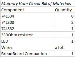
List of Materials
This shows the amount of each material needed to create the circuit on a breadboard. The breadboard companion is the green part shown in the pictures below.
|
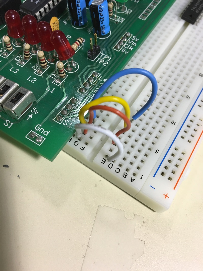
First I placed wires from each switch to the breadboard. In this photo the white is the President, the red is the Vice President, the yellow is the Secretary and the blue is the Treasurer.
|
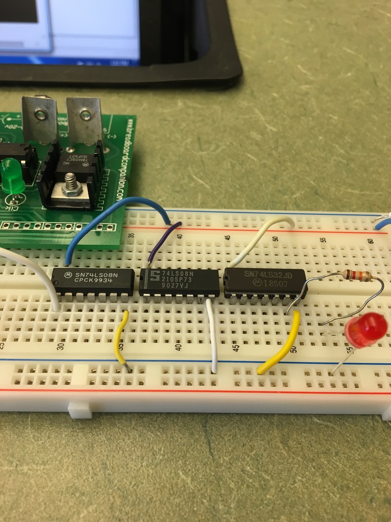
Then I grounded and powered each IC chip to the breadboard. I also placed the resistor and diode.
|
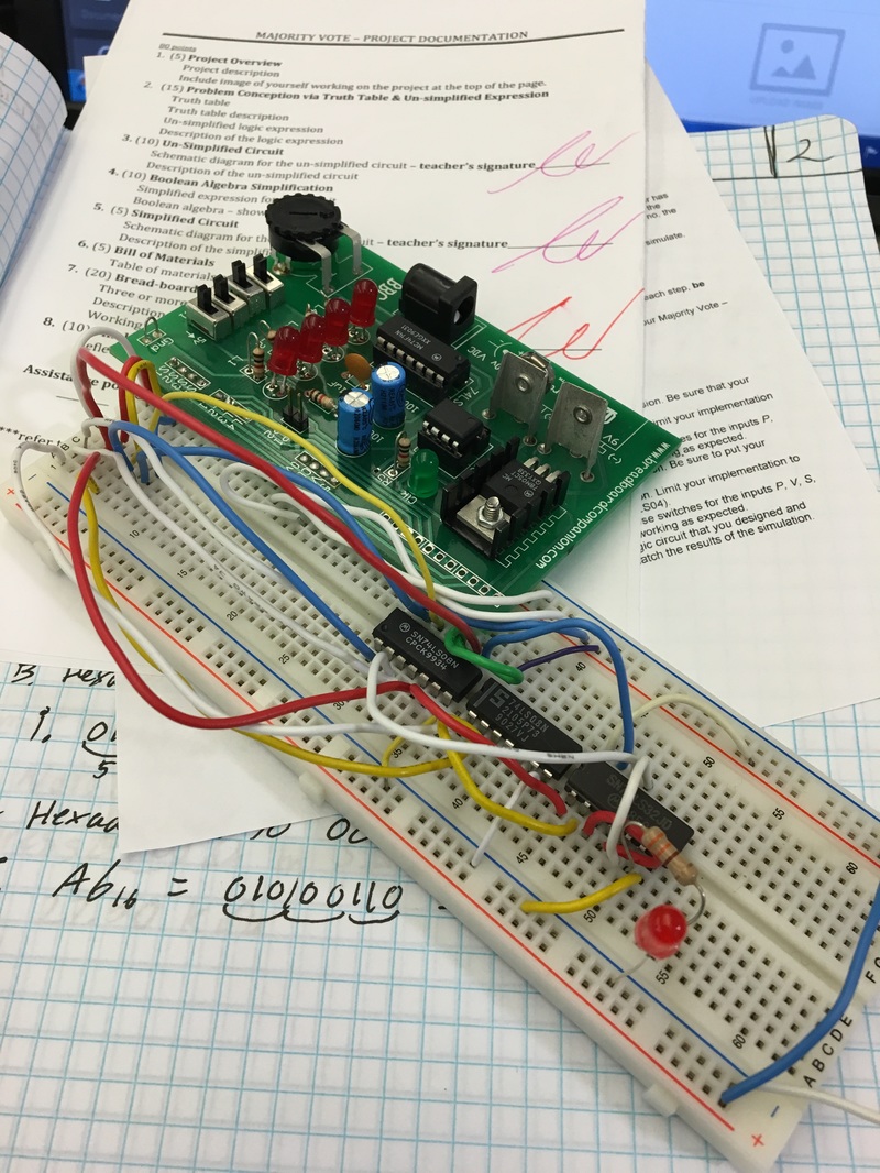
This photo was taken after I had wired and color coded by breadboard to make it easier to detect issues if I were to have any.
|
I created my Breadboard correctly on my first try but when I plugged it into a power source the diode would light up in any position except when all 4 switched were in the on position. I assumed there was a wiring issue so I redid my entire circuit and made it in the same way but color coordinated my wires. Once the circuit wasn't functioning properly. It turned out that my resistor was pushed in too far and was touching the diode and this made the circuit overheat and not function properly. After fixing that the circuit worked perfectly.
Conclusion
This project went fairly well and my only issue was from the resistor being pushed in too far into the breadboard. Some important things to take from this son is to check all the components and make sure that they are all inserted properly. Also, color coding your wires helps a lot to make the circuit easier to understand and fix if you need to trouble shoot. This taught out the basic understanding of how to go from a statement to an actual circuit. The first step is to make a truth table that satisfies the conditions given by the statement. Then you should write out the minterms that satisfy the condition in the sum of products form. From here you want to use Boolean algebra and consensus theorems to get a simplified logic expression. Then you should create the circuit on a software program to help you envision how to create the circuit on a breadboard. Boolean algebra is a life saver and really helps you make sense of your un-simplified expression. By simplifying the expression, you can save a lot of money since you cut out a lot of gates that you didn’t need for the circuit to function. Overall this project showed the importance of Boolean algebra and helped us learn more about how to use IC chips.
