illustration credits to http://www.deviantart.com/art/Eridan-Ampora-WALLPAPER-345804670
Compound & Simple Machines
Our Team
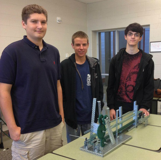
From left to right: Egor Reznikov, Ryan Sauer, Ian Waggoner (me)
Design Brief
Gantt Chart
Decision Matrix
Brainstorming
We didn't take much time to come up with a design but our initial thoughts were a conveyor belt that would be powered by a lever that would move a can two feet. Then we thought of adding a gear train to make moving the conveyor belt easier. The conveyor belt is a chain and sprocket system. Other thoughts we had were to suspend the can and make it act like a zip line but that wouldn't meet the requirements or be reliable. We also came up with a few other combinations, like a pulley system powered by a lever that would lift the can and then roll it down an inclined plane. Another idea was some of crane with a lever that spun horizontally, turning a horizontal gear train and then a vertical chain and sprocket system that would turn an arm at the top that would swing the can.
We didn't take much time to come up with a design but our initial thoughts were a conveyor belt that would be powered by a lever that would move a can two feet. Then we thought of adding a gear train to make moving the conveyor belt easier. The conveyor belt is a chain and sprocket system. Other thoughts we had were to suspend the can and make it act like a zip line but that wouldn't meet the requirements or be reliable. We also came up with a few other combinations, like a pulley system powered by a lever that would lift the can and then roll it down an inclined plane. Another idea was some of crane with a lever that spun horizontally, turning a horizontal gear train and then a vertical chain and sprocket system that would turn an arm at the top that would swing the can.
Preliminary Sketches
|
|
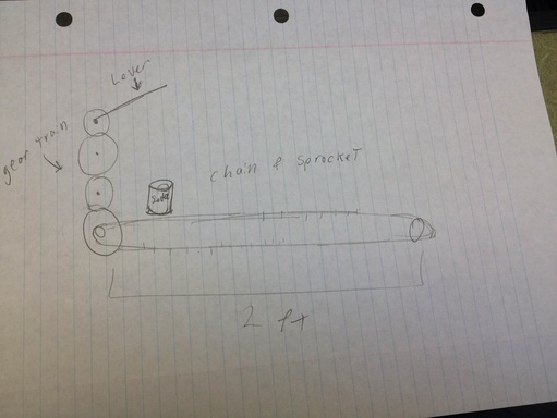
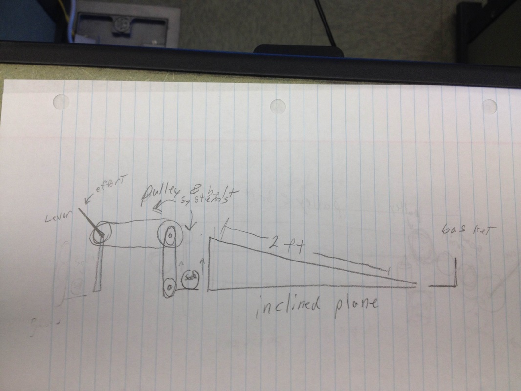
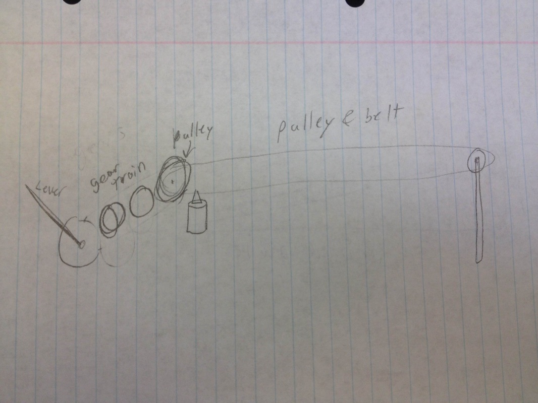
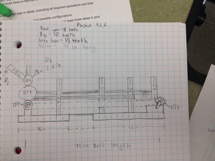
The first photo shows a lever turning a pulley and belt system that would raise the soda can and then roll it onto an inclined plane. The second one shows a Lever moving a gear train which in turns moves the pulley and belt system from which the soda can is suspended. the third sketch is the one we ended up using, it shows a lever turning a gear train which moves a chain and sprocket system which acts a conveyor belt to move the soda can
Final Sketch
Ryan drew the final sketch
Building Process, Testing Results, Modifications
When we first got our supplies we immediately went for the Conveyor belt idea, we found a chain that was over two feet and found two gears that would fit, we also added a third gear in the middle for support. We got the base plate and screwed vertical metal structures to it which we used to anchor our gears. Then, on the opposite side of one of the metal structures we started creating a gear train upwards to where our lever would be. By turning the top gear we tested how the chain moved and if it was smooth. The movement was jerky most likely because the axle was square and the hole it was in was also square so we mad a modification and fund rubber parts with circular whole and attached those to the metal structures. This greatly improved the movement of the chain.
After fixing that, we made the lever by attaching a 7.5 inch metal structure to a gear on the same axle as the topmost gear. The lever made it much easier to move the chain and enabled us to turn it faster.
Once we had finished we tested it a few times with a can of soda. One of our biggest issues were that the can tended to fall off the track. So, some final modifications we made were adding railing so that the can wouldn't out and the addition of a small basket at the end of the chain where the can would fall into.
Final Design
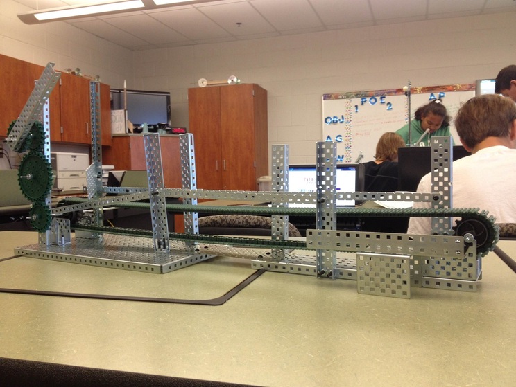
The green gears to the left is our gear train and on the top of it is the lever. On the same axle as the bottom gear is the first gear of our Chain and Sprocket system. the metal protrusion at the right hand side is the basketinto which the can will fall.
Final Calculations
Our total mechanical advantage was 6, which we derived from the IMA of the lever and our total gear ratio was 1 which was the gear ratio of the gear train and the chain and sprocket system.
Conclusion Questions
1. The gear train was the simplest to calculate. The drive ratio for gears can be (number of teeth (out)/ number of teeth (in)). The reason this was so simple was simply that the input gear and the output gear were the same gear so the gear ratio was 1.
2. The lever was definitely the hardest to calculate considering that everything else was just 1. We did the effort distance divided by the resistance effort. the effort distance was the length of the handle, 7.5 inches, and the resistance distance was the radius of the gear it was attached to which was 1.25 inches. so 7.5/1.25 equals 6.
3. If were to apply 20 lbs of force to the lever, the output force would be 120 lbs. I got this answer form the equation of output force equals mechanical advantage * input force. The mechanical advantage i used was six which is the MA of the lever.
4. I think that by having using a smaller input gear than the output gear would have increased the gear ratio and made the machine more efficient. also maybe by adding a pulley system we could have increased the total mechanical advantage by having multiple strands.
