Overview

|
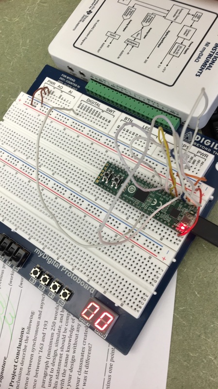
In this project we created a device that counts form zero to sixty and then restarts. It does not show 60 but goes back to zero when detected.
|
PLD Circuit
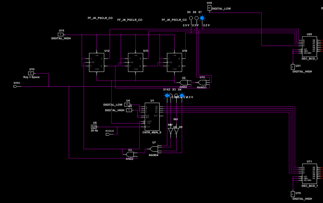
This project is extremely similar to the 80 counter except for a few things. One thing is that the 80 counter displayed 80 and the paused, this circuit does not display 60 and restarts after displaying 59. Also, this circuit uses a 74ls163 chip and JK flipflops. this circuit features a reset button that is very similar to the 80 counter.
Conclusions
|
1. Asynchronous counters have each flip flop wired to each other such the the output of the first flip flop is the input for the second one. In synchronous circuits, the clock goes directly to each flipflop's input.
2. A '163 chip displays the number it detects, can only count up, and has a synchronous load and clear. A '193 chip displays the number before the number it detects, can count up or down, and has asynchronous loads and clears. 3. First I created the least significant digit circuit using the 74ls163 chip. I connected A through D to ground so that the count would begin at zero. Then I wired the outputs to a 4 input NAND gate such that it would detect a 9, or 1001 in binary. This output then goes through an AND gate whose other input is from the reset button. This goes to the load input on the ‘163 chip so that the LSD circuit resets to zero after detecting 9. The output also becomes the input of the first JK flip flop of the most significant digit circuit. The MSD circuit consists of three JK flip flop. The J, K, and Preset pins of each flip flop is connected to power. The not Q output of the first two flip flops are connected to the input of the second and third flip flops, respectively. There is a three input NAND gate that detects 6, or 110 in binary. When it detects the six, it sends a signal to and gate which is also connected to the reset button. The signal goes to each clear pin of the Flip Flops and to the clear pin of the ‘163 chip causing both digits to reset to zero. The reset button overrides the count at any time, resetting it to zero and starting the count again. The Q outputs of both circuits go to individual decoders which are then wired to a system of multiplexers so that the digits can be displayed on two displays. 4. Some students implemented an inverter into their reset button to fix an error where the circuit only works if the reset is activated and held in the activated position. |
|
