|
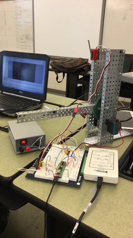
Here is the Working Prototype in all its glory. |
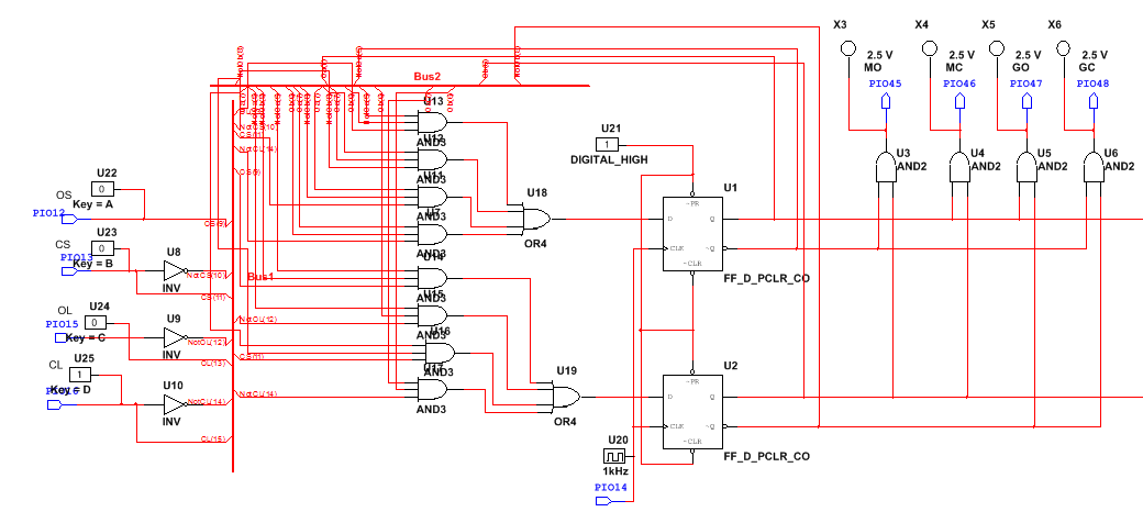
MultiSim
Conclusion
This project involved a lot of thought prior to designing the circuit. First we made a state graph showing the sequence of events that the toll booth would go through. It had to have 4 different states: closed, opening, open, and closed. Also when the booth was closed it had to light up an LED and when open it had to light a different LED. Then we had to design a state table that would allow us to create the Boolean expressions necessary for the circuit. We had to create Boolean expressions for the data input of both flip-flops and each of the four outputs. Many of the conditions were “don’t care” situations which greatly aided in the developing of the expressions. This project was fairly similar to other projects in the sense that you simply had to derive expressions from a truth table and transfer it to a circuit. It was different in how we had to use a state graph and then use the circuit to move a vex structure that we had to make. The only mistake we made is that we didn’t align the wires with the correct pins and they were off by 1. This was easily fixed by moving them all down one pin. Next time I would try to count properly. In this project we also had to use a schematic to wire a chip that interpreted information from the PLD and took power from the power source to power the motor. Reading this schematic was much easier than earlier in the year because I didn’t overthink the schematic and just wired where it told me to.
